Overview
Let’s start with a directional light. It casts shadows all over the scene. Since it is a directional light, it has infinite range and thus casts shadows everywhere. If we stretched a shadow map over the entire world, the shadow resolution would simply not be sufficient. We only want to casts shadows that the user might actually see. That is, shadows that will be cast onto objects within the view frustum of the screen being rendering. This tutorial is intended to provide an efficient method for finding the bare minimum of objects that could potentially be casting shadows into the view of the observer.
Frustum Culling
You should already be familiar with frustum culling. A frustum is basically a specialized form of a k-DOP with 6 sides or planes. A k-DOP is basically a set of planes that enclose a volume, always in a convex manner. If a point is in front of every plane in the k-DOP, it is inside the volume described by the k-DOP.
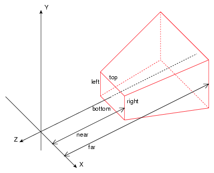
The planes of a frustum are called the left, right, top, bottom, near, and far planes. Though they don’t have to be named in specifically that order, defining a specific order for the planes will be necessary for this process.
It doesn’t matter if the projection is orthographic or perspective; either way it is just 6 planes that enclose a space. One key thing to point out, however, is that these planes face inward, towards the inside of the space they enclose.
Culling objects out of this box involves a bounding-box test, usually against the object’s AABB or OBB, or even bounding sphere. In general, AABB’s are not quite as accurate, but still preferable for their simplicity in testing and updating. I use a min-max AABB, and here is the basic structure:
	/**
	 * Class CAabb
	 * \brief A min-max axis-aligned bounding box.
	 *
	 * Description: A min-max axis-aligned bounding box.
	 */
	class CAabb {
		// == Members.
		/** The minimum X-, Y-, and Z- axis values. */
		CVector3		m_vMin;

		/** The maximum X-, Y-, and Z- axis values. */
		CVector3		m_vMax;
	};
It is simply the minimum and maximum values along each axis. These are easy to update as the object moves through the world. I have omitted the rest of the class for the sake of brevity.
Treating a frustum as a k-DOP (an array of planes), I will present an algorithm for checking to see if an AABB is inside, intersecting, or outside of a k-DOP (a k-DOP implies a predetermined orientation for the planes, which will not be our case, but for lack of better terminology we will stick with “k-DOP”). First we must enumerate these cases.
	/**
	 * Intersection.
	 */
	enum LSM_PLANE_INTERSECT {
		LSM_PI_FRONT,
		LSM_PI_BACK,
		LSM_PI_INTERSECT,
	};
The first step is to classify the AABB to a plane. Here, _pPlane.n is its normal and _pPlane.dist is its distance.
	/**
	 * Classifies an axis-aligned bounding box in relation to a given plane.
	 *
	 * \param _aAabb The AABB to test against the given plane.
	 * \param _pPlane The plane to test against the given AABB.
	 * \return Returns a plane classification.
	 */
	LSE_INLINE LSM_PLANE_INTERSECT LSE_CALL CClassify::Aabb( const CAabb &_aAabb, const CPlane3 &_pPlane ) {
		// Center of the AABB.
		CVector3 vC = (_aAabb.m_vMax + _aAabb.m_vMin) * LSM_HALF;
		// Positive extents.
		CVector3 vE = _aAabb.m_vMax - vC;

		// Compute the projected interval radius of _aAabb onto L(t) = _aAabb.c + t * _pPlane.n.
		LSREAL fR = vE[0] * CMathLib::Abs( _pPlane.n[0] ) +
			vE[1] * CMathLib::Abs( _pPlane.n[1] ) +
			vE[2] * CMathLib::Abs( _pPlane.n[2] );

		// Distance from box center to plane.
		LSREAL fS = _pPlane.n.Dot( vC ) - _pPlane.dist;

		// If less than R, return overlap.
		if ( CMathLib::Abs( fS ) <= fR ) { return LSM_PI_INTERSECT; }
		// Otherwise it is in front or back of the plane.
		return fS > fR ? LSM_PI_FRONT : LSM_PI_BACK;
	}
Now that we can classify an AABB in relationship to a plane, testing it against a k-DOP is trivial. First, my k-DOP class:
	/**
	 * Class CCappedKDop
	 * \brief A k-DOP with a maximum number of planes when performance is needed.
	 *
	 * Description: A capped k-DOP is a k-DOP with a maximum number of planes.  This stores enough planes to hold the
	 *	maximum, so allocations are avoided, making this the choice for a limited number of planes in high-performance
	 *	situations.
	 */
	template <unsigned _uMax>
	class CCappedKDop {
	public :
		// == Various constructors.
		LSE_INLINE LSE_CALLCTOR			CCappedKDop() :
			m_ui32Total( 0UL ) {
		}

		// == Operators.
		/**
		 * Give array access.
		 *
		 * \param _ui32I The index of the plane to retrieve.
		 * \return Returns the plane at the given index, which must be valid.
		 */
		LSE_INLINE CPlane3 & LSE_CALL		operator [] ( LSUINT32 _ui32I ) {
			assert( _ui32I < m_ui32Total );
			return m_pPlanes[_ui32I];
		}

		/**
		 * Give array access.
		 *
		 * \param _ui32I The index of the plane to retrieve.
		 * \return Returns the plane at the given index, which must be valid.
		 */
		LSE_INLINE const CPlane3 & LSE_CALL	operator [] ( LSUINT32 _ui32I ) const {
			assert( _ui32I < m_ui32Total );
			return m_pPlanes[_ui32I];
		}

		// == Functions.
		/**
		 * Get the total number of planes in this k-DOP.
		 *
		 * \return Returns the number of planes in the k_DOP.
		 */
		LSE_INLINE LSUINT32 LSE_CALL		TotalPlanes() const {
			return m_ui32Total;
		}

		/**
		 * Add a plane.
		 *
		 * \param _pPlane The plane to add.
		 * \return Returns false if a memory failure prevents the adding of the plane.
		 */
		LSE_INLINE LSBOOL LSE_CALL		AddPlane( const CPlane3 &_pPlane ) {
			if ( m_ui32Total < _uMax ) {	// Could be changed to assert().
				m_pPlanes[m_ui32Total++] = _pPlane;
				return true;
			}
			return false;
		}

		/**
		 * Reset the list of planes.  Very fast.
		 */
		LSE_INLINE LSVOID LSE_CALL		Reset() {
			m_ui32Total = 0UL;
		}

	protected :
		// == Members.
		/** The array of planes. */
		CPlane3					m_pPlanes[_uMax];

		/** The actual total of planes. */
		LSUINT32				m_ui32Total;
	};
A k-DOP can have any number of planes, but usually there is a finite limit. For example, frustums always have 6 planes, and the k-DOP we will build for the meat of this tutorial can have a maximum of 13 (thanks to floating-point errors). Instead of dynamically allocating planes, I use a template to specify a maximum number of planes, and let the k-DOP scale within that limit.
Also note that I am declaring and defining the class at the same time. This is for brevity; you should be putting function definitions below the class declaration.
And finally, to check if an AABB is fully or partially inside a frustum:
	/**
	 * Determines if the given AABB is partially or entirely inside the k-DOP.
	 *
	 * \param _aabbBox The axis-aligned bounding box to test for being contained by the given k-DOP.
	 * \param _kdDop The k-DOP to test for containment.
	 * \return Returns true if the AABB is partially or entirely inside the k-DOP.
	 */
	template <unsigned _uMax>
	LSE_INLINE LSBOOL LSE_CALL CTest::AabbKDop( const CAabb &_aAabb, const CCappedKDop<_uMax> &_ckdDop ) {
		for ( LSUINT32 I = _ckdDop.TotalPlanes(); I--; ) {
			if ( CClassify::Aabb( _aAabb, _ckdDop[I] ) == LSM_PI_BACK ) { return false; }
		}
		return true;
	}
If the AABB is behind any of the k-DOP planes, it is outside of the k-DOP. Remember that the k-DOP planes face inward towards the inside of the frustum.
It is wise to have a second version that additionally returns a boolean that indicates if the AABB is fully inside the k-DOP, but that is an exercise for the reader.
This tutorial is not really about culling things from the observer’s view, it is about culling objects that could cast shadows not seen by the observer. However, all of these structures and functions are used for both tasks, so this brief overview of standard frustum culling serves as a warmer to the meatier things to come.
Examining a k-DOP for the Directional Light
Our next goal is to find out what objects can cast shadows that will be visible by the observer. We want to include everything the observer can see, and also some objects that are out-of-sight in the direction away from the directional light (that is, towards the source of the light). In order to do this, we will construct another k-DOP which acts like a projection of the frustum in the opposite direction of the directional light (towards its source).
Let’s look at how the observer’s frustum may look from the light’s point of view.
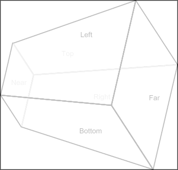
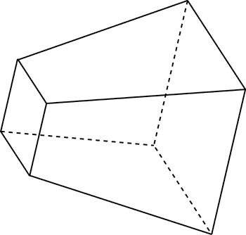
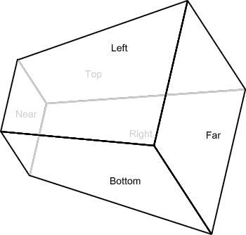
Here, the light is above and behind the player a bit, and is looking down on him. Notice the lack of perspective divide. The near, top, and right planes are closer to us.
What is the shape of the k-DOP we want to form? Well, first we will want the planes of the frustum that form the “back planes” from the light’s perspective.
Refer to the original image to see that the greyed lines are closer to us than the black ones. The black ones here represent the 3 back planes from the light’s point-of-view. That is, the bottom, far, and left planes. We can figure out which planes are the back planes easily enough through a simple dot product. If the dot product between the plane normal and the light direction is negative, we keep the plane. The below image illustrates why.
Now for the whole reason I am writing this tutorial. What other planes do we need to add? Let’s say we are given the 8 corner points of the frustum. We know where in space each of the corners is, and from the light’s point of view we are looking at them.
What if we found the farthest points in the up, left, right, and down directions and added planes in the form of a box, as shown below?

The black lines represent 4 planes that are each the extremes in their respective directions among the 8 corner points in the frustum. The lines are flat because the planes would be coming directly towards us, as we are the source of the light.
This is fairly simple, but it has a huge potential to add objects to the shadow maps that don’t need to be there. What we actually want is a tight fit around the outline of the frustum as shown below.

We want this black outline extruded infinitely towards the source of the light.
So how do we do that? How do we know which points to use as the outline? And can we make sure the planes we add are always pointing towards the inside of the volume? Well, if there is a Part 2 to this tutorial, I assume it has more content than just “No”, so stay tuned and find out.
L. Spiro


Hello. And Bye.